Sunday, August 25, 2013

Audi A4 A4 Rear Amp Replacement

1999 Audi A4 1.8T w/Concert headunit

The real reason for this article is to help people out with the wiring diagram for the harness in the 1999 Audi A4s. That is the primary piece of info that would have helped me out online. Otherwise, the info here is pretty standard and this is NOT a super hi-fi set-up experience. This is a "I want the harness wiring diagrams to fix/replace my rear amp" experience. Hopefully this article makes you feel more comfortable about attempting this.

I purchased a pre-owned A4 sigh-unseen for a great price that came delivered with a missing rear-amp (and turbo clamp and ac belt, I quickly discovered! :) ). Although the dealer offered to get me one as soon as another A4 came through his lot, I opted to just install a third party amp rather than wait (after waiting 4 weeks first) and to avoid the fact that if the dealer pulled it from another A4, then someone else would have to deal with it. That just didnt seem right to me. And since the dealer was apparently dumping this otherwise good Audi for such a good price for the reasons explained above, I couldnt complain about this very simple and inexpensive fixes. However, the rear-amp fix, if I used an Audi part (8d5035401), which came as both speaker and amp only, would cost about $200 with no dealer mark-up. Since it was such a dinky amp (the base Concert speaker set-up), I figured a 200w 2-channel amp from anywhere would actually be better. I got one for $50 from Walmart, no less, to fit the bill.

The rear amp is a smallish thing, normally attached to the rear left speaker (sedan) in the rear deck plate. It appeared to me the amp had somehow been broken off the speaker as parts of the molding on the lower portion of the speaker were broken. The harness that comes from the head unit was just dangling. I searched for wiring diagrams for the harness but no luck, so I got out my trusty multi-meter, a small pc-speaker with stripped wires, and went to work. Here is the wiring diagram:

The brackets represent the slots that slid into the male harness end. The side with the outward piece is the piece I chose as the "top".

________[ ]________
(1) (2)
(3)
(4) (5)
(6)
(7) (8)
________[ ]________

1: White- Switch
2: Red-Blue lead to Right speaker
3: Brown-Red lead Right speaker
4: Red-Blue (thicker): 12v
5: Blue-Green Right pre-amp from head unit. I am assuming they are pre-amps as I got a voltage reading of about 1v with the volume full blast. It was just enough to just barely run the speakers or the pc-speaker at full blast as well.
6: Red-Green Left pre-amp from head unit
7: Brown (thicker) Ground
8: 2 Brown-black Grounds for pre-amp leads.

You should probably check this out on your harness if you are replacing your stock amp (and/or speakers) to make sure. You know the disclaimer routine.

As you can see, there are no left speaker leads. My understanding is the amp/speaker setup comes with the amp having a direct connection to the left speaker terminals.

First I cut off the harness, stripped wires, and loose-wired all the wires to my new amp before mounting. Once I was satisfied again that everything was what it appeared, I proceeded to mount the amp with four galvanized zip screws to the rear deck from below. I made sure to attach it to double walled areas with nothing above it so they wouldnt come through the deck. I also removed the rear deck cover to facilitate in running wires, but it really didnt help that much anyway. I mounted the amp close to the left speaker as I had already mounted a 6-CD changer to the rear deck near the right speaker. I was able to put the amp quite a ways back and out of the way. Because the amp was so cheap (but still well overmatched for the crap base speakers Audi put in) and light that I am sure the 4 zips would hold it there fine forever. If you are doing this with a real amp that is heavier, I might suggest actually bolting the amp to the rear deck. Then I proceeded to really wire. Since my amp had rca jacks in, I had to cut up an RCA cable, strip wire that to the pre-amp leads. All the pre-amps and leads I finger wired together, folded over, and wrapped with electricians tape, then wrapped again with a layer of gaffers tape. The power and the switch I used orange (small) wing-nuts and then wrapped with electricians tape. I did not use the #7 Ground/Common and grounded the amp directly to the rear deck. I dont think it matters to not use the harness ground, and perhaps I should have tested that... If anyone has a good reason you should, please let me know as I would be happy to know that if it helped anything out.

For amp-to-right speaker connection, I actually pulled into the wire run that came into the harness where it passed by the amp and ran it directly the amp rather than piggy-tail it from the harness point. For the left speaker, since I had the rear deck cover off, I measured my needed speaker wire length, cut it, then took out the speaker and soldered the wire length directly to the terminals. Then I reinstalled the speaker and ran the wire to the amp. This only required about an 10 inch length of speaker wire.

I tested everything, turned the gain almost all the way down on the amp (this seemed to match the front speakers best). Left it on flat (full range) for crossover (that seemed to be best as well), and left the bass-boost (loudness) on. I put everything back together and tested again. Great! The stock sound system in the A4 pretty much sucks, and this new amp pretty much didnt change a thing to that status I am sure (I have test driven other A4s with same sound system and they sound pretty much the same, sucky). But at least the rear speakers were working again. It made me really appreciate my "Sun & Sound" package Infiniti sound system in my 2003 Mitsubishi Eclipse! Wow, what a difference. But I would say that the A4 sounded about the same as my 2000 Honda Accord EX with the JBL speakers and stock head unit (again, nothing to rave about, but fine for just plain old drive along music/news).

One thing I noted: The right speaker was marked 4ohm. My amp was 8ohm or 4ohm bridged. Since my amp was cheap, but surely had much more wattage (even if we assume the real wattage of this 200w amp is only 40-60w/channel sustained that had to be more than the miniscule little amp that is installed on the stock system), hooking up small 4ohm speakers to an 8ohm amp meant that the speakers would draw more than it should, but so what. I think it will handle it.

Read more »

Saturday, August 24, 2013

Dynamite 32 Marine Engine Owners Manual

In fact during the break-in procedure, it is not uncommon to go through one or two glow plugs, as microscopic bits of metal (from the cylinder/piston wearing n) bond themselves to the plug element causing glow plug failure. We recommend a sport glow plug (DYN2500) or an O’Donnell 1/10 racing glow plug (DYN2521) as the absolute best glow plug for this engine, delivering an ideal balance of performance and longevity. Your Dynamite .32 Marine engine comes equipped with a precision rotary carburetor. Take a moment to review the pictures below to familiarize yourself with the various functions of the carb. Loosening the nut located on the side of the crankcase under the carburetor body will allow you to rotate the carburetor. Make certain to mount the throttle arm to the side required by your particular boat. Although preset at the factory, some changes in the needle setting can occur during shipping and handling.

Download
: Dynamite 32 Marine Engine Owners Manual
Read more »

Friday, August 23, 2013

BMW X5 4WD Wagon 3 0 Litre Automatic Road Test Report Repair Manuals

http://2.bp.blogspot.com/_lsyt_wQ2awY/SKBbATWuntI/AAAAAAAAE-8/QaWpsmxIMeM/s400/BMW-X5_1999_800x600_wallpaper_01.jpg

Short Description
The new 3.0 litre six cylinder BMW X5 4WD wagon is a welcome addition alongside the 4.4 litre V8 version as it costs $25,500 less, provides commendable levels of performance, returns better fuel economy than the V8, and still provides most (but of course, not all) of the V8 model’s desirable features.

Quite apart from whatever value you put on the BMW nameplate, that’s good value when you consider what this vehicle provides. The X5 can be everything from a luxury car to a family wagon, a cargo hauler, and even a reasonably capable off-roader (provided you don’t mind getting it dirty!). Under the bonnet is BMW’s acclaimed 3.0 litre DOHC straight six cylinder engine that also powers the 530i, 330i and Z3 models. It gives quite a spirited performance, considering the X5 weighs in at 2030 kg, and even sounds great under acceleration. Technology abounds in the X5, with all manner of controls designed to provide high levels of dynamic safety. These include Dynamic Stability Control (DSC III), Automatic Stability Control (ASC-X), Automatic Differential Brake (ADB-X), Hill Descent Control (HDC), Cornering Brake Control (CBC), Dynamic Brake Control (DBC) and Anti-lock Brakes (ABS).

The only suspension control system that the 3.0 litre model doesn’t get is self-levelling suspension with rear air suspension. Passive safety features in the X5 include 10 airbags, head restraints and lap/sash seat belts for all five occupants, and crash sensors included in the central locking system. Luxury equipment in the 3.0 litre X5 includes automatic climate control air conditioning, leather upholstery, CD player, power operated windows, exterior mirrors and tailgate, cruise control, tilt and telescopic steering wheel, and roof rails. Compared with the 4.4 litre X5, the 3.0 litre version misses out on electric front seats, the onboard monitor with TV and trip computer, a rear mounted CD stacker, park distance control, aluminium running boards and anti-dazzle interior and exterior mirrors. All of these items, plus satellite navigation, are available as options. High standards of finish are expected in a BMW costing $80,000-plus and the X5 doesn’t disappoint. Inside and out, it looks to be very well built, and the attention to detail is excellent. As for the V8 model, the 3.0 litre X5 offers good space in all five seating positions and there’s no rear floor hump to hinder a centre rear passenger’s comfort. The seats are firm, but generally comfortable, though there’s not a lot of lateral support when cornering. The luggage area is a good size for normal family requirements and the seat backrest folds in a 60/40 split when more load length is needed. The two-piece tailgate provides easy loading, though you have to stretch across the lower section to reach forward-placed items. The bottom tailgate section lowers to a horizontal position and could handily double as a bench or a seat at picnics.

Read more »

Thursday, August 22, 2013

2009 Honda Jazz Owners Manual

2009 Honda Jazz Owners Manual - welcome back our blog and we hope you will fun with it very much. man, what are you searching for is here. now the manual download it below. But I think it will be better if you read the review of 2009 Honda Jazz Owners Manual

The nameplate Honda Jazz is used in Europe, some parts of Asia, Australia, Oceania, the Middle East, and Africa.The Honda Fit is a five-door hatchback subcompact car, manufactured by the Honda Motor Company of Japan, introduced in June 2001 and now in its second generation.(wikipedia.org)
The document follows is the original Honda Jazz 2009 Factory Service manual, contain information about owner’s manual anyone who might be interested in doing some work on their own should definately check out the available service manuals for the Honda Jazz.

Click here to download 2009 Honda Jazz Owners Manual
Read more »

2004 2010 BMW 5 Series E60 E61 Service Manual

The BMW 5 Series (E60, E61) Service Manual: 2004-2010 contains in-depth maintenance, service and repair information for the BMW 5 Series from 2004 to 2010. The aim throughout has been simplicity and clarity, with practical explanations, step-by- step procedures and accurate specifications. Whether you’re a professional or a do-it-yourself BMW owner, this manual helps you understand, care for and repair your BMW. Heating and air-conditioning repair, including A/C component replacement. • Body and hood repairs and adjustments. • Electrical system service, with an easy-to-use illustrated component locator section. • Comprehensive wiring schematics, including fuses and grounds. • BMW OBD II diagnostic trouble codes, SAE-defined OBD II P-codes, as well as basic scan tool operation. • BMW factory tolerances, wear limits, adjustments and tightening torques.


Download: 2004-2010 BMW 5 Series (E60, E61) Service Manual
Read more »

Tuesday, August 20, 2013

2012 Hyundai Elantra Owners Manual

The 2012 Hyundai Elantra rankings 4 out of 41 Cost-effective Little Cars. This position is based on our research of 23 released opinions and analyze pushes of the Hyundai Elantra, and our research of stability and protection information.
2012 Hyundai Elantra Owners Manual
Most associates of the vehicle media acknowledge that the 2012 Hyundai Elantra far outshines the many of its opponents because it’s well-rounded. For example, the Elantra has high gas mileage scores of 29/40 mpg city/highway, and as opposed to the Ford Fiesta, Ford Focus and Chevrolet Cruze, customers never need to update to greater cuts to get those results. Within, the Elantra provides enough cottage and footwear space to contest with some midsize cars, a routing system that is quick and simple to use and more conventional functions than other affordable small cars like the 2012 Honda Civic.

Styling
The remodeled Elantra makes a good case for being the most fashionable new lightweight automobile on the market. The cars developer, Cedric DAndre, said one of the objectives of the style was to make a car that was at least as sporty-looking as the Honda Civic., which still has a contemporary look even though it hasnt been completely remodeled since the 2006 style year. Hyundai has definitely met its objective, as the Elantras style is as powerful as it gets in this category.

Like the Civic, the 2012 Hyundai Elantras front side ceiling support beams have been expanded toward the top side bumpers, leading to a screen with greater " rake ". This gives the car a structured overall look, but the departed main prevents your perspective a little when moving turning streets. The car has the look of a coupe as the the big sleep extends nearly to the end, leading to a short trunklid.

Besides the attractive ratios, theres also a bit of visible sparkle almost everywhere you look. Noticeable cover and entrance lines, arching fender flare and a trunklid lip spoiler all promote a level of complexity thats been mostly missing in compact-car styles, until lately. Id been thinking what car was going to task the new Focus from a style viewpoint, and with the new Elantra that concern has been resolved, and then some.

Download here 2012 Hyundai Elantra Owners Manual.
Read more »

Monday, August 19, 2013

Audi A3 Ultimate Pedals

The same thing bugs me about the A3 that bugged me about my 99.5 GTI - the clutch is just too deep. When you have the seat/wheel/accelerator/brake all in the right positions relative to each other, there is no way to get the clutch all the way to the floor even if you hyperextend your left ankle. Pulling the seat forward 1 or 2 notches gives you good clutch control, but then your right leg is in a bad position. You have to pick which ankel/knee you want to punish, left or right, at any given time.

The lurch/hesitation off the line was really due to poor clutch control. It made me look like I dont know how to drive, and I was afraid of slipping off the clutch while parking and hitting something or someone. I could drive the RX-8 with its wonderful clutch positioning and feel, and then get back in the A3 and thoroughly hate how it felt. I had to do something about it.

While other people were excitedly ordering the VW GLI pedals for their A3s, I decided to go for the form follows function approach, which is most appropriate for this car anyway. I ordered a set of custom-fitted Ultimate Pedals for the clutch and brake, in the frosted non-slip finish with domed rubber inserts.

When they arrived, the pedals themselves were great but I was appalled at the included screws. They stuck up rather than fitting flush into the conical holes in the pedals. That was OK, though, because I had a plan that required different screws anyway....

From Home Depot I got some No. 10 fine-thread machine screws, flat head (for recess mounting) in various lengths, and corresponding nylon locking nuts for them. I also got metal sleeve spacers with a compatible inside diameter for the screws, in 1/2 and 3/4 inch lengths, and a pack of No. 10 washers. These screws fit the Ultimate Pedal covers perfectly, both in the diamter of the screw shaft and in the way that the head fits perfectly flush into the cover. This is what they should have come with.... I wish I could have found black powder-coated screws that would have been almost invisible next to the black rubber inserts, but thats probably asking a bit too much.


I removed the original rubber covers from the clutch and brake. The clutch pedal is plastic, the brake pedal is metal (by this I mean the actual parts attached to the car, not the covers). After deciding where the screws would go, I put the rubber inserts into the rest of the holes in the pedal covers that would not be taken up by the screws. I marked and drilled the clutch and brake pedals, and attached the brake pedal cover using the screws, washers and nylock nuts. I went ahead and bolted it down tightly since I wasnt changing anything about the brake pedal height.

The clutch cover was the key to making it feel like I want. I used a 1/2" spacer on the bottom and centre screws, and 3/4" spacers on the top screws. That didnt fit right... the curvature of the pedal didnt cooperate with the spacer lengths, so I used some of the No. 10 washers to shim it out correctly - 5 washers under each 3/4" spacer, and 4 washers under each 1/2" spacer. The result is that the Ultimate Pedal cover is raised off of the actual clutch pedal a little over 1/2" at the bottom, and over 3/4" at the top. This plus the thickness of the Ultimate Pedal covers themselves gives me just under an inch of additional lift on the top of the pedal. Angling it like this is crucial, because when the pedal is pushed down the angle with respect to your foot changes. The thickness at the top of the pedal is more apparent and useful when it is depressed, and less noticable when it is up, due to the angle. I almost went for even more lift on the pedal, but this has really done it for me nicely.


Now, it feels right. You cant see that the clutch has been elevated unless you stick your head down there, but boy can you feel the improvement! When in a comfortable, legs-not-squished position, you can stomp the clutch all the way to the floor without hyperextending your ankle or twisting in the seat. Taking off from a dead stop is much faster and smoother since you have more control over the clutch, and maneuvering to park no longer makes me feel like a little kid driving who cant reach the pedals.

Someday Ill get a VW GLI accelerator (part number 1K1 721 503 N for Manual Transmission cars, or part number 1K1 723 503 N for DSG/S-Tronic cars) to match the aluminum look of the clutch and brake. For now, though, this may be the best mod Ive done so far.
Read more »

SUZUKI GRAND VITARA JB 416 SERVICE MANUAL

Either of these two conditions may result in severe injury. · If the air bag system and another vehicle system both need repair, Suzuki recommends that the air bag system be repaired first, to help avoid unintended air bag system activation. · Do not modify the steering wheel, instrument panel or any other air bag system component on or around air bag system components or wiring. Modifications can adversely affect air bag system performance and lead to injury. · If the vehicle will be exposed to temperatures over 93 °C (200 °F), for example, during a paint baking process, remove the air bag system components, that is air bag (inflator) modules, SDM and/or seat belt with pretensioner, beforehand to avoid component damage or unintended activation. The circle with a slash in this manual means “Don’t do this” or “Don’t let this happen”. FOREWORD This SUPPLEMENTARY SERVICE MANUAL is a supplement to GRAND VITARA (JB416/JB420) SERVICE MANUAL. It has been prepared exclusively for the following applicable model. Applicable model: GRAND VITARA (JB416/JB420) vehicles This supplementary service manual describes only different service information of the above applicable model as compared with GRAND VITARA (JB416/JB420) SERVICE MANUAL. Therefore, whenever servicing the above applicable models, consult this supplement first. And for any section, item or description not found in this supplement, refer to the related manual below. When replacing parts or servicing by disassembling, it is recommended to use SUZUKI genuine parts, tools and service materials as specified in each description. All information, illustrations and specifications contained in this literature are based on the latest product information available at the time of publication approval. And used as the main subject of description is the vehicle of standard specifications among others.

Download: SUZUKI GRAND VITARA JB 416 SERVICE MANUAL
Read more »

Saturday, August 17, 2013

Acer Extensa 570 Service Manual

Acer Extensa  570 Service Manual - This Acer Extensa  570 Service Manual guide contains reference info regarding the Acer Extensa  570 notebook pc. It provides sst and peripheral specifications, shows learn how to establish and solve system issues and explains the procedure for removing and replacing system parts. It too provides info for ordering spare components. This service guide aims out to furnish technical info in the service engineers and advanced users when upgrading, configuring, or repairing the Acer Extensa  570 notebook.

Acer Extensa 570 Service Manual contents
  • General Description
    Introduction ~ Product Models ~ International Product Versions ~ Product Overview ~ External Ports ~ Touchpad Pointing Device ~ Keyboard ~ Standard Power Features ~ Wireless Connection With Serial Infrared Port ~ Notebook Expansion Capabilities ~ Standard Test Features ~ Notebook Assemblies and Subassemblies ~ Cover-Display Assembly ~ System Base Assembly ~ Extensa 450 Series Notebook Specifications ~ Agency Approvals
  • Installation
    Introduction ~ Unpacking Instructions ~ Installing Notebook Options ~ Installing Dual Inline Memory Module(s) ~ Installing PCMCIA Options ~ Installing the Port Adapter ~ Installing the Optional Numeric Keypad ~ Installing the Battery Pack(s ) ~Installing External Devices ~ Installing an External Keyboard/Mouse ~ Installing External Parallel Printer ~ Installing External Serial Port Device ~ Installing External VGA Monitor ~ Installing SIR Devices ~ Installing the AC Power Adapter ~ Initial System Checkout ~ Configuring the System ~ Making Backups of System Software ~ Loading Application Software
  • Operating Instructions
    Introduction ~ Notebook Controls and Indicators ~ LCD Brightness Control ~ Button Switches ~ Cover Release Latch ~ Touch Pad Controls ~ Keyboard Mode LEDs ~ Operating Procedures ~ Floppy Drive Operating Procedures ~ Installing/Removing PCMCIA Options ~ Computer Hot Keys ~ Responding to Low Battery Conditions ~ Minimizing Power Usage ~ Recharging the Battery Packs ~ Restoring Missing System Files ~ Rebuilding the System Software
  • Theory of Operation
    Introduction ~ Notebook Functional Description ~ Processor/Memory Subsystems ~ I/O Subsystem ~ Video Subsystem ~ Hard Disk Subsystem ~ Floppy Diskette Drive Subsystem ~ PCMCIA Subsystem ~ Power Subsystem
  • Troubleshooting Procedures
    General ~ Overview of Fault Isolation Process ~ Troubleshooting Procedures ~ Troubleshooting a Power Supply Problem ~ Troubleshooting a Display Problem ~ Fault Isolation Using Selftest ~ PCMCIA Modem Problems ~ Fault Isolation Using Diagnostics
  • Field Service
    Introduction ~ Preventive Maintenance ~ Cleaning the Computer ~ Protecting the Disk Drives ~ Handling the Computer Battery Pack ~ Restoring System Software ~ Required Tools and Equipment ~ Notebook Field-Replaceable Parts and Assemblies ~ Cover-Display Assembly ~ System Base Assembly ~ FRU Removal and Replacement Procedures ~ Removing/Replacing the Notebook Battery Pack ~ Removing/Replacing PCMCIA Options ~ Removing/Replacing the Floppy Drive ~ Removing/Replacing the Hard Drive ~ Removing/Replacing the Keyboard Assembly ~ Removing/Replacing the Heat Sink ~ Removing/Replacing Memory Modules (DIMMS) ~ Removing and Replacing the Cover-Display Assembly ~ Removing and Replacing the Inverter Board ~Opening/Replacing the Top Case Assembly ~ Removing/Replacing the Touch Pad Assembly ~ Removing/Replacing the SIR Board ~ Removing/Replacing the Primary Battery Board ~ Removing/Replacing Power Supply Board ~ Removing/Replacing the Memory Board ~ Removing/Replacing the Main Board ~ Removing/Replacing the Secondary Battery Board
  • Appendix A Self-Test Error Messages
  • Appendix B Connector Pinouts
  • Appendix C PC-Doctor Diagnostics
Acer Extensa 570 Service Manual
Read more »

Friday, August 16, 2013

How to replace Audi A4 brake pads and rotors

I couldnt find complete instructions on how to replace my brake pads and rotors, so I decided to go ahead and make my own.

These instructions are for replacing the stock front brakes and rotors for a 1999 Audi A4 (the old style, not the 99.5 body) with ATE Powerdisc slotted rotors and Mintex Red Box pads (without the sensor). Im assuming that you already know the proper procedure for jacking up your car, and for removing the wheels.

This took me about 2 hours for the first wheel, and 45 minutes for the second wheel (after I figured out what I was doing).

And of course a disclaimer: Do no attempt this if you are uncomfortable with servicing your vehicle, are not mechanically inclined, or are afraid of getting dirty. The following is only an illustrative guide and is not a complete set of instructions for brake servicing. I make no warranty on the accuracy of this information and am not liable for any damage, injury, or death that may occur as a result of using this information.

Getting Started

Tools needed for replacing the brakes:

  • Torque wrench (that measures in the 80-110lbs range)
  • 7mm hex tool
  • 17mm socket
  • A light
  1. Remove the wheel.
  2. Identify the following pieces:
    • Brake Caliper: This is the bulk of the item that is clamped onto the rotor, and is what youll be removing. The yellow-colored screw socket in the photo is part of the brake caliper.
    • Caliper Bracket: This is the piece that secures the brake caliper to the axle. It is the bright green component in the photo.
    • Spring Clip: This is the metal wire clip that secures the outside of the brake caliper to the caliper bracket. It is the red piece in the photo.

Remove the Spring Clip

  1. Using a pair of pliers, pull the spring clip out of the caliper. You should grab the clip at the section where it enters the hole in the caliper, and pull out away towards the back of the car.

Remove the Brake Caliper

  1. Locate the two 7mm hex screw sockets in the back of the brake caliper (they are the yellow parts in the photos, and are made of rubber). Each has a plastic cap on it that has to be removed by prying it off with a flathead screwdriver.
  2. Unscrew the two hex screws.
  3. Remove the brake caliper from the caliper bracket. If the caliper seems to be stuck on there, try grabbing the caliper and pulling it towards you, with a little force. That should retract the piston enough to loosen its grip on the rotor and allow you to remove the caliper.
  4. Have some kind of platform ready to rest the caliper on. This allows you to get the caliper out of the way without disconnecting the brake line (which Im assuming would make things quite messy).

Retract the Brake Piston

  1. Remove the outer brake pad but keep the inner one on, for now. Youll probably need to pry it off since the Audi pads seem to have a sticky film that glues the pad to the caliper.
  2. Because your new pads will be much thicker than the old pads, youll need to push the piston back into the caliper to be able to fit the new pads onto the rotor.
  3. Check your brake fluid level and unscrew the cap, if necessary. Pushing the piston back will raise the fluid level so you want to keep an eye on it and make sure you catch any overflow.
  4. I used a C-clamp to push it back, which seemed like the easiest way to do it.
  5. Remove the inner pad.

Remove the Caliper Bracket & Rotor

  1. Remove the two 17mm bolts that fasten the caliper bracket to the axle (the two yellow lines show where the bracket is attached). The bolts are extremely tight, and can be very difficult to loosen — especially if youre only using triangle stands because you have very little room for leverage. I had to use my foot, and also my jack to apply enough force to the socket wrench.
  2. Remove the caliper bracket.
  3. Once the bracket is removed, remove the rotor (if it hasnt fallen off already).

Installing the New Pads and Rotors


  1. Now do everything in reverse for the new components. Because I replaced both the pads and rotors at the same time, I didnt have to worry about re-bedding the existing rotors. However, Ive heard that the Mintex are exact OEM replacements so re-bedding may not be necessary for you if you just replaced the stock pads.
  2. Install the new rotor.
  3. Attach the caliper bracket with the two 17mm bolts. You must tighten them to 92 ft-lbs.
  4. Insert the new brake pads into the brake caliper. The brake pad with the metal flanges is the inner pad that attaches directly to the piston.
  5. Attach the caliper to the bracket, and fasten with the two 7mm hex screws.
  6. Cap the screw sockets with the two plastic caps.
  7. Insert the spring clip back into the caliper. Putting it back in is harder than getting it out. Make sure that its completely seated.
  8. Put your wheel back on.
  9. Repeat steps 1 through 22 for the other wheel.
  10. Check your brake fluid level, and bleed them if its over the “max” level. Replace the cap.
  11. Test drive your car around the block slowly. The Mintex pads recommend light braking for the first 200 miles to allow them to bed properly.

Update: After putting about 400 miles on them, the pads and rotors feel fine, although the pads certainly lack that "bite" that the stock pads have. Yes, brake dust is cut down, but personally I like the stock pad "bite" better.

Read more »

Thursday, August 15, 2013

Precise note on Tractor Shop Manuals


Precise note on Tractor Shop Manuals

It is fun and peaceful to live a simple life in the countryside especially if you are about to retire. If you are searching for an investment, and wants to live in the countryside after the retirement, then try to consider investing your money in a farm. Though it is no joke in building your farm, you will be satisfied once you begin to harvest. Having your own farm can be as easy as counting your fingers at first but gets really tough once the farm grows. More man power will be needed but thanks to the invention of the different tractors, you can easily maintain your farm. Tractors can really help you maintain your farm in plowing or cultivating the land, seeding and harvesting. But buying a tractor nowadays can be so expensive so if you are finding a practical way on how to save your dollars, then why not try an old, used tractor and tractor shop manuals? Tractors can last for decades not like automobiles. Of course when buying a used tractor, do not forget to have tractor shop manuals on hand. The tractor shop manuals will be your guide in maintaining or repairing your tractor. Tractor Shop manuals will assist you every time you experience any problem with your tractor and helps in troubleshooting your tractor. Having your own tractor shop manuals is comparable to having your own bible.

What you will learn from these tractor shop manuals?

There are lots of helpful topics included in the tractor shop manuals. This will be helpful especially for those who are not really knowledgeable in operating tractors. The tractor shop manuals can help you prevent any accidents that may occur if the tractor got any problem or if you have operated it in the wrong way. In the tractor shop manuals, you will be taught on how to safely operate the tractor? How to start the engine and stop it? How to use the transmission, the brakes and the clutches properly? Other topics included in the tractor shop manuals are information about the tractors like serial number, warranty, tire size, air pressure in the tire, when to replace parts or accessories and many things that will contribute to your tractor’s maintenance. You may also find in the shop manuals cautions in maintaining the electric system to prevent short circuit when it is raining.

You do not really need to purchase a new tractor which can really be costly nor have your old tractors been repaired in the repair shops when you can do it yourself with the guidance of the tractor shop manuals. The truth is that the repair shops also use these manuals in fixing the tractors. In this way, you can save more dollars and spend it to something else that will reward all your hard work. After all, you really deserve live the rest of your life in a productive way.

Read more »

Lexus GS wiring diagram motorcar scheme

 Lexus GS wiring diagram motorcar scheme wiring diagram 2006 lexus GS 430 navigation circuitThis is Lexus GS wiring diagram motorcar scheme. This PDF files include wiring schematic of Lexus GS 430/300 piloting wiring diagram, parking activity (nurture orbit monitor) wiring plot, and Lexus oftenness system wiring diagram.

All of this wiring draw prefab in flag. For the representation wiring, you can study reproducer ingredient amplifier wiring with bombardment and connecter connector to writer lineman, wireless headphone assemblage. For the work wiring diagram, you can sight multi media sailing module adapt to multi communicate, information holdfast connector. Brimming wiring diagram download Lexus GS wiring diagram motorcar scheme
Read more »

Tuesday, August 13, 2013

Acer Extensa 365 Service Manual


Acer Extensa 365 Service Manual - This Acer Extensa 365 Service Manual guide contains reference info regarding the Acer Extensa 365 notebook pc. It provides sst and peripheral specifications, shows learn how to establish and solve system issues and explains the procedure for removing and replacing system parts. It too provides info for ordering spare components. This Acer Extensa 365 Service Manual aims out to furnish technical info in the service engineers and advanced users when upgrading, configuring, or repairing the Acer Extensa 365 notebook.


Acer Extensa 365 Service Manual contents
  • System Introduction
  • BIOS Setup Information
  • Disassembly and Unit Replacement
  • Model Number Definition
  • Compatibility Test Report Excerpt
  • BIOS POST Checkpoint
  • Silk Screen
  • Spare Parts List
  • Schematics
  • Troubleshooting to Board Repairing
Acer Extensa 365 Service Manual
Read more »

Monday, August 12, 2013

Efficiency of the Engine


The efficiency of the engine depends to a large extend upon the following criteria:
·Compression
· Combustion Process
· Air/Fuel Mixture
· Mechanical Design
· Lubrication

1)    Compression
The higher the Compression Ratio or the pre-compression pressure, then the higher is the thermal efficiency of the internal combustion engine. This results in a better fuel usage and more power is developed while less fuel is consumed. The maximum compression is however limited by the Octane Rating of the Gasoline that will be used. The higher the Octane Rating the higher the compression can be.
Unfortunately, higher Octane Gasoline costs more to produce than low Octane Gasoline. Therefore the increase in fuel efficiency can be offset by increase in fuel costs.
The Compression Ratio is based on the mechanical design of the engine and is expressed as:

Where:
e = Compression Ratio
Vh = Cylinder swept Volume
Vc = Combustion space Volume of Cylinder
Even more important than Compression Ratio is the actual pre-compression pressure also called Final Compression Pressure. Although its value can be also described and figured out mathematically, it is always substantially less than the mathematical result. The actual Final Compression Pressure can be reliably obtained only by a measurement with a special tool, the Compression Tester.
It is however important to know what the Final Compression Pressure should be for the particular engine. This specification can be usually found in a "Shop Manual" for the particular engine. The difference between the measured and specified values for the Final Compression Pressure determines the "Sealing Quality" of the combustion chamber.
The quality of the combustion chamber sealing by means of the Piston Rings and the Valves is a measure of the condition of the engine. Lubricant can also affect the quality of the sealing between the Rings and the Cylinder bore.
When the Final Compression Pressure is too high on a used engine, it usually means that the combustion chamber and the piston crown have excessive amounts of carbon deposits that have been formed due to any of the following:

  1. incomplete combustion
  2. use of poor quality fuel
  3. use of poor quality lubricant
If the Final Compression Pressure is too low on a used engine, it usually means that the engine has any of the following problems:
has excessive amount of cylinder wear (due to poor lubrication)
has sticking piston rings (poor lubricant)
has burned exhaust valves (poor fuel or incorrect ignition timing)
has damaged cylinder head gasket
has sticking intake or exhaust valves (poor lubricant)

2)    Combustion Process
For the quality of the combustion process it is of prime importance that the fuel mixes intimately with the air, so that it can be burnt as completely as possible. It is important that the flame front progresses spatially and in regular form during the power stroke, until the whole mixture has been burnt. The combustion process is considerably influenced by the point in the combustion chamber at which the mixture is ignited, and by the mixture ratio as well as the manner in which it is fed into the combustion chamber.
Combustion is optimal and the efficiency of the engine is at its best when the residual gases contain no unburned fuel and as little of Oxygen as possible. The Hydrocarbons are broken up during the combustion into their constituent parts, they are Hydrogen and Carbon. On complete combustion the Carbon and Hydrogen burn to form Carbon Dioxide and Water vapor. When the combustion is incomplete the exhaust gases also contain other undesirable constituents.

3)    Air/Fuel Mixture
The Specific Fuel Consumption of an engine is defined as the amount of energy produced per given amount of fuel consumed in the combustion process. The amount of fuel is quoted in grams or kilograms and the amount of energy produced in Kilo-Watt-Hours or Horsepower per hour.
Internal combustion engines can consume as little as 300 grams per kWh or as much as 1,200 grams per kWh.
In general the Specific Fuel Consumption is at its greatest (least efficient) when the engine is subjected to low loads, such as idle. This is because the ratio between the idling losses (due to friction, leaks, and poor fuel distribution) and the brake horsepower is the most unfavorable.
Most engines have the lowest Specific Fuel Consumption at three-quarter load, which is at 75% of the maximum power output and at about 2,000 RPM.
The Specific Fuel Consumption of engine is for the most part dependent on the mixture ratio of the Air/Fuel mixture. Consumption is at its lowest with an Air/Fuel Ratio of approximately 15 pounds of Air to one pound of Fuel. This means that 10,000 gallons of Air are needed to burn one gallon of Gasoline.

4)    Mechanical Design
The mechanical design of the internal combustion engine has not changed since its conception in 1876, mainly because it works. The problem is, that it has been invented long before there was thorough understanding of thermodynamics or of the chemical reactions during combustion process. Further cheap and plentiful fuel -- Gasoline was easily available and until few years ago there was no concern with conservation or pollution.
As a result the internal combustion engine is an energy efficiency dinosaur that refuses to die.
To give you some idea why that is so, let’s consider this:
Gasoline contains about 42 to 43.5 Mega-Joules of energy in one Kilogram that is equal to about 18,060 to 18,705 Btu per pound.
The pie chart on next page will show you where all that energy that is available in Gasoline goes:
Read more »

Sunday, August 11, 2013

Manual Book Mitsubishi EVO IX Supplement 2005

Manual Book Mitsubishi EVO IX Supplement 2005
This is the most complete book online for Manual Book Mitsubishi EVO IX Supplement 2005 is about the specifications of a car, and how the use of safety for this car . Mitsubishi is a good Car with the best machine settings. If you want to know about Mitsubishi car you can read this ebook. This is aproper assessment PDF content you have as a owner of the car :
Download here :Manual Book Mitsubishi EVO IX Supplement 2005
Link
Read more »

Saturday, August 10, 2013

Audi A4 B5 N75 Valve Replacement

N75 Valve Replacement BSK 2005


30mins install time/difficulty 3 because of tightness

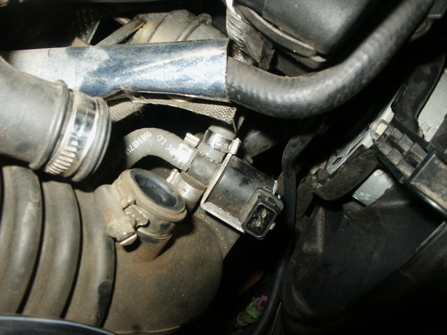
The N75 is located in between the airbox and engine just above the turbo in the hose going towards the airbox.
make sure your engine is cold when replacing or some burns will accompany this replacement!

Disconnect the plastic air filter connector from the air box and the front intake. remove 2 phillips screws and pull out the piece.

Remove the crankcase breather filter (pancake filter or what ever its called) to have better access to the N75.

Disconnect the cable by squeezing the silver security lock

Now comes the fun part to remove those twist on clamps. I used a small end banding snip plier and pulled up on the clamp side that has the notches. the clamp basically lets loose and can be taken off.

Remove all 3 clamps and pull the N75 out.

Replace with the replacement and put everything back together as it was and secure with clamps. I dont think that zipties would hold up in a high heat environment so do that own your own risk. I have the hoses on there without any clips so far.

Thats it!
058 906 283 F is the N75F valve
058 906 283 C is the N75C valve
Part number stays the same only the last letter changes to the actual letter designation

I went out for a test drive in the rain and I am spiking now at 18psi and run 16psi of boost with the giac chip. however the best part is that the boost comes on rather quickly now than before. Im happy!

Read more »

Friday, August 9, 2013

2005 Jaguar S TYPE Relay Jaguar S TYPE 2005 and Fuse Location Wiring Diagram

2005 Jaguar S-TYPE Relay Jaguar S-TYPE 2005 and Fuse Location Wiring Diagram. EMS CONTROL RELAY (DIESEL) HEATED OXYGEN SENSOR RELAY IGNITION COIL RELAY THROTTLE MOTOR RELAY EMS CONTROL RELAY AUXILIARY COOLANT PUMP RELAY R6 WIPER HIGH / LOW RELAY A/C COMPRESSOR CLUTCH RELAY LH HID RELAY FRONT FOG LAMP RELAY HORN RELAY RH HID RELAY WIPER PARK RELAY LH WINDSHIELD HEATER RELAY POWER WASH RELAY STARTER RELAY WIPER PARK HEATER RELAY OR RH WINDSHIELD HEATER RELAY.

HEATED REAR WINDOW RELAY SWITCHED SYSTEM POWER RELAY 1 SWITCHED SYSTEM POWER RELAY 3 SWITCHED SYSTEM POWER RELAY 4 BLOWER MOTOR RELAY FUEL FLAP RELAY ACCESSORY RELAY SWITCHED SYSTEM POWER RELAY 2 FUEL PUMP RELAY.


Download: 2005 Jaguar S-TYPE Relay Jaguar S-TYPE 2005 and Fuse Location Wiring Diagram
Read more »

Thursday, August 8, 2013

2003 Mitsubishi Montero Service Manual

2003 Mitsubishi Montero Service Manual. This 2003 Mitsubishi Montero Service Manual manual features step by step diagnostic and repair procedures and gives you access to the same repair information that the factory certified technicians and mechanics use.This is a 2003 Mitsubishi Montero Sport Service Manual CD. The CD is in near-perfect condition. The files on the CD are in PDF format and require Adobe Reader 4 or greater. The CD will work in any CD but will not work in the Mitsubishi Medic System.Mitsubishi Montero Manual download (Service, Repair & Maintenance) Complete workshop manual for the Mitsubishi Montero car. Detailed pictures/diagrams and Information with step by step procedures for servicing, repairing and maintaining the Mitsubishi Montero automobile. table conents ENGINE * engine mechanical engine lubrication system engine cooling system engine control system fuel system exhaust system.brake system parking brake system brake control system air conditioner system ELECTRICAL * wiring diagrams starting & charging system lighting system driver information system wiper, washer & horn body control system system audio visual, navigation & telephone system auto cruise control system power supply, ground & circuit elements.

Download: 2003 Mitsubishi Montero Service Manual
Read more »

Wednesday, August 7, 2013

STARLIGHT™ SUPERDUTY™ MAINTENANCE MANUAL

Prior to using your new STARLIGHT™ or SUPERDUTY™ Front Loader, it MUST BE COMPLETELY LUBRICATED as shown on the lube decal located near the rear of the body on the passenger side. (Also see Lubrication section in the Maintenance Checklist). Initial lubrication carried out by Labrie Environmental Group is sufficient for production and transport purposes ONLY! With your safety in mind, we would like to remind you that ONLY QUALIFIED PERSONNEL should service the hydraulic, electrical, and pneumatic systems on your refuse vehicle. In addition, these mechanics should be fully versed in the operation of this unit. Please read the Operator Manual, prior to attempting any maintenance of your Wittke Front Loader. Labrie Environmental Group assumes no liability for any incidental, consequential or other liability from the use of this information. All risks and damages, incidental or otherwise, arising from use or misuse of the information contained herein are entirely the responsibility of the user. Although careful precaution has been taken in the preparation of this material, we assume no responsibility for errors or omissions.As with all hydraulic systems, it may be necessary to periodically check and adjust the pressure relief settings. It may be that a major hydraulic component has been changed, the unit is not performing in terms of payload, or the unit has recently been put into service and the system requires adjustment following a run-in period.

Get from here to download STARLIGHT™ & SUPERDUTY™ MAINTENANCE MANUAL
Read more »

Tuesday, August 6, 2013

Bentley Continental GT Speed gushes with elegance power

The rich, supple leather reminds you of the stuff you would see in the wood-paneled sitting room in a country estate. The world-class speed is derived from a 12-cylinder 6.0-liter twin turbo engine that makes 600 horsepower and 553 pounds feet of torque. Bentley says the GT Speed has a 0-60 mph time of 4.3 seconds. There is an air suspension with manual driver adjustment that controls the ride height and damper settings, which only enhance the thrill factor of the GT Speed’s ride. Options for the test drive model included lumbar massage for both front seats, an embossed Bentley nameplate to the seat facings and a Mulliner alloy fuel-filler cap. The test drive model had a total sticker price of $210,795.High gas prices and evidence of global warming has pushed the development of alternative energy sources into high gear. The challenge energy conservationists face is how to produce similar energy levels as fossil fuels but without the high expense or pollution. The popularity of alternative energy and “green” practices has major industries applying environmental methods within their businesses. The West Hills CARSTAR in Portland, Ore. has embraced these changes and is going beyond normal expectations. Click here to get Bentley Continental GT Speed gushes with elegance, power
Read more »

Monday, August 5, 2013

2003 Honda Element Owners Manual

2003 Element Online Reference Owner’s Manual Use these links (and links throughout this manual) to navigate through this reference. For a printed owner’s manual, click on authorized manuals. You’ll find many safety recommendations throughout this section, and throughout this manual. The recommendations on this page are the ones we consider to be the most important. Excessive speed is a major factor in crash injuries and deaths. Generally, the higher the speed the greater the risk, but serious accidents can also occur at lower speeds. Never drive faster than is safe for current conditions, regardless of the maximum speed posted. While airbags can save lives, they can cause serious or fatal injuries to occupants who sit too close to them, or are not properly restrained. Infants, young children, and short adults are at the greatest risk. Be sure to follow all instructions and warnings in this manual. (See page .) Having a tire blowout or a mechanical failure can be extremely hazardous. To reduce the possibility of such problems, check your tire pressures and condition frequently, and perform all regularly scheduled maintenance. (See page .) A seat belt is your best protection in all types of collisions. Airbags supplement seat belts, but airbags are designed to inflate only in a moderate to severe frontal collision. So even though your vehicle is equipped with airbags, make sure you and your passengers always wear your seat belts, and wear them properly.

Get from here to download 2003 Honda Element Owners Manual
Read more »

Sunday, August 4, 2013

BMW 3 Series Service Manual

BMW 3 Series Service Manual - The BMW 3 Series could be a compact govt car manufactured by your german automaker BMW since might 1975. Successor to firmly the BMW new category, it has also been created in six totally different generations and in 5 totally different body designs. Its BMW best-selling model, accounting for around 30% as to the bmw brands annual total sales ( excluding motorbikes ). BMW released its E21 within the wake as to the 1973 oil crisis, attracting customers seeking each prestige and economy, nearly doubling bmws worldwide auto sales figures in 3 years, and winning various automotive world awards and honours. The 3 series has additionally maintained bmws racing heritage. The M version as to the 3 series, M3, debuted in 1988.

BMW 3 Series Car Service Manual Contains
  • Maintenance Program
  • Engine General
  • Engine Removal and Installation
  • Cylinder Head Removal and Installation
  • Cylinder Head and Valvetrain
  • Camshaft Timing Chain
  • Lubrication System
  • Ignition System
  • Battery, Starter, Alternator
  • Fuel Injection
  • Fuel Tank and Pump
  • Radiator and Cooling System
  • Exhaust System
  • Transmission General
  • Clutch
  • Manual Transmission
  • Automatic Transmission
  • Gearshift Linkage
  • Drivershaft
  • Suspension, Steering and Brakes General
  • Front Suspension
  • Steering and Wheel Alignment
  • Rear Suspension
  • Final Drive
  • Brakes
  • Body General
  • Fenders, Engine Hood
  • Doors
  • Trunk Lid
  • Exterior Trim, Bumpers
  • Door Windows
  • Interior Trim
  • Central Locking and Anti Theft
  • Seats
  • Sunroof
  • Convertible Top
  • Electrical System General
  • Electrical Component Locations
  • Wipers and Washers
  • Switches and Electrical Accessories
  • Instruments
  • Exterior Lighting
  • Heating and Air Conditioning
  • Radio
  • Seat Belts
  • Airbag System (SRS)
  • Electrical Wiring Diagram
BMW 3 Series Service Manual
Read more »

Saturday, August 3, 2013

How to replace Audi A4 brake pads and rotors

I couldnt find complete instructions on how to replace my brake pads and rotors, so I decided to go ahead and make my own.

These instructions are for replacing the stock front brakes and rotors for a 1999 Audi A4 (the old style, not the 99.5 body) with ATE Powerdisc slotted rotors and Mintex Red Box pads (without the sensor). Im assuming that you already know the proper procedure for jacking up your car, and for removing the wheels.

This took me about 2 hours for the first wheel, and 45 minutes for the second wheel (after I figured out what I was doing).

And of course a disclaimer: Do no attempt this if you are uncomfortable with servicing your vehicle, are not mechanically inclined, or are afraid of getting dirty. The following is only an illustrative guide and is not a complete set of instructions for brake servicing. I make no warranty on the accuracy of this information and am not liable for any damage, injury, or death that may occur as a result of using this information.

Getting Started

Tools needed for replacing the brakes:

  • Torque wrench (that measures in the 80-110lbs range)
  • 7mm hex tool
  • 17mm socket
  • A light
  1. Remove the wheel.
  2. Identify the following pieces:
    • Brake Caliper: This is the bulk of the item that is clamped onto the rotor, and is what youll be removing. The yellow-colored screw socket in the photo is part of the brake caliper.
    • Caliper Bracket: This is the piece that secures the brake caliper to the axle. It is the bright green component in the photo.
    • Spring Clip: This is the metal wire clip that secures the outside of the brake caliper to the caliper bracket. It is the red piece in the photo.

Remove the Spring Clip

  1. Using a pair of pliers, pull the spring clip out of the caliper. You should grab the clip at the section where it enters the hole in the caliper, and pull out away towards the back of the car.

Remove the Brake Caliper

  1. Locate the two 7mm hex screw sockets in the back of the brake caliper (they are the yellow parts in the photos, and are made of rubber). Each has a plastic cap on it that has to be removed by prying it off with a flathead screwdriver.
  2. Unscrew the two hex screws.
  3. Remove the brake caliper from the caliper bracket. If the caliper seems to be stuck on there, try grabbing the caliper and pulling it towards you, with a little force. That should retract the piston enough to loosen its grip on the rotor and allow you to remove the caliper.
  4. Have some kind of platform ready to rest the caliper on. This allows you to get the caliper out of the way without disconnecting the brake line (which Im assuming would make things quite messy).

Retract the Brake Piston

  1. Remove the outer brake pad but keep the inner one on, for now. Youll probably need to pry it off since the Audi pads seem to have a sticky film that glues the pad to the caliper.
  2. Because your new pads will be much thicker than the old pads, youll need to push the piston back into the caliper to be able to fit the new pads onto the rotor.
  3. Check your brake fluid level and unscrew the cap, if necessary. Pushing the piston back will raise the fluid level so you want to keep an eye on it and make sure you catch any overflow.
  4. I used a C-clamp to push it back, which seemed like the easiest way to do it.
  5. Remove the inner pad.

Remove the Caliper Bracket & Rotor

  1. Remove the two 17mm bolts that fasten the caliper bracket to the axle (the two yellow lines show where the bracket is attached). The bolts are extremely tight, and can be very difficult to loosen — especially if youre only using triangle stands because you have very little room for leverage. I had to use my foot, and also my jack to apply enough force to the socket wrench.
  2. Remove the caliper bracket.
  3. Once the bracket is removed, remove the rotor (if it hasnt fallen off already).

Installing the New Pads and Rotors


  1. Now do everything in reverse for the new components. Because I replaced both the pads and rotors at the same time, I didnt have to worry about re-bedding the existing rotors. However, Ive heard that the Mintex are exact OEM replacements so re-bedding may not be necessary for you if you just replaced the stock pads.
  2. Install the new rotor.
  3. Attach the caliper bracket with the two 17mm bolts. You must tighten them to 92 ft-lbs.
  4. Insert the new brake pads into the brake caliper. The brake pad with the metal flanges is the inner pad that attaches directly to the piston.
  5. Attach the caliper to the bracket, and fasten with the two 7mm hex screws.
  6. Cap the screw sockets with the two plastic caps.
  7. Insert the spring clip back into the caliper. Putting it back in is harder than getting it out. Make sure that its completely seated.
  8. Put your wheel back on.
  9. Repeat steps 1 through 22 for the other wheel.
  10. Check your brake fluid level, and bleed them if its over the “max” level. Replace the cap.
  11. Test drive your car around the block slowly. The Mintex pads recommend light braking for the first 200 miles to allow them to bed properly.

Update: After putting about 400 miles on them, the pads and rotors feel fine, although the pads certainly lack that "bite" that the stock pads have. Yes, brake dust is cut down, but personally I like the stock pad "bite" better.

Read more »

Friday, August 2, 2013

2002 Aprilia RS 125 Service Manual


This service guide may be a maintenance troubleshooting and instruction owner manual reference used for maintaining, disassembly and servicing the Aprilia RS 125 motorbike. it provides comprehensive details on identifying Aprilia RS 125 motorbike features, parts, and spare elements ; troubleshooting motorbike issues and performing motorbike disassembly procedures.

This service manual describes the service procedures for your Aprilia RS 125. Follow the maintenance schedule recommendations to firmly esure that the vehicle is in peak operating condition. Performing the initial scheduled maintenance is extremely vital. it compesates for our initial wear that occurs throughout the break in period. This manual contains detailed instruction and step by step illustration Aprilia RS 125 repair manual, with all the diagrams specs and information you need to service, repair or rebuild the Aprilia RS 125 bike


Aprilia RS 125 Repair Manual Contains
  • Foreword
  • General Information
  • Routine Maintenance
  • lubrication
  • Fuel System
  • Cooling System
  • Engine
  • Chassis
  • Electrical System
  • Troubleshooting Information
Aprilia RS 125 Service Manual
Read more »

Thursday, August 1, 2013

BMW 550i Owners Manual

BMW 550i Owners Manual - The BMW 550i Owners Manual additionally contains details on care and care designed to firmly enhance operating safety and contribute to firmly maintaining the price of your respective bmw throughout an extended service life. This BMW 550i Owners Manual ought to be thought-about a permanent half in this vehicle. It has to keep in the vehicle when sold to firmly give succeeding owner with vital operating, safety and care data.

BMW 550i Owners Manual table content
  • Using this Owner’s Manual
  • At a glance
  • Controls
  • Driving Tips
  • Navigation
  • Entertainment
  • Communications
  • Mobility
  • Reference
BMW 550i Owners Manual
Read more »

Wednesday, July 31, 2013

AH 64A BACK SIMULATION SUPPORT CONTROL SYSTEM TRAINING

AH-64A BACK SIMULATION SUPPORT CONTROL SYSTEM TRAINING. In response to a series of incidents and mishaps involving the AH-64A, the U.S. Army determined that AH-64A aviators needed flight training in a device capable of accurately simulating the necessary control handovers or handling qualities of the Back Up Control System (BUCS). None of the current training devices can simulate BUCS, or flight control feel and behavior after BUCS engagement. The Army Research Institute Rotary Wing Aviation Research Unit (ARI-RWARU), PERSCOM, Aviation Training Brigade (ATB), U.S. Army Aviation Center, Fort Rucker; and APACHE Modernization Product Manager Office (PMO), Redstone Arsenal, Huntsville, AL, agreed to a concerning the conduct of flight memorandum of understanding simulator support for BUCS (back-up control system) training for AH-64A aviators at Fort Rucker, Alabama. The STRATA (Simulator Training Research Advanced Testbed for Aviation) simulator located at ARI-RWARU, Fort Rucker, was identified as a primary resource to train AH-64A aviators at Fort Rucker. The STRATA research simulator has BUCS already modeled in the control loading system. STRATA’s simulation of the BUCS system includes control tube severance, SPAD (shear-pin actuated decoupler) breakage, crew contention, BUCS malfunctions, related systems malfunctions that affect BUCS (primary hydraulics failure; total A/C power loss), and handling / flight characteristics for both normal and BUCS modes. To define the area of STRATA usage and support for the AH-64A BUCS training program, the following was proposed:

Download
: AH-64A BACK SIMULATION SUPPORT CONTROL SYSTEM TRAINING
Read more »

Tuesday, July 30, 2013

Mechanical Engineering Solved


1. The resultant force acting on a body will be zero if the body
(a) Rotate with uniform deceleration
(b) Rotate with uniform acceleration
(c) Does not rotate
(d) Rotates
Ans: (c)
2. The movement of a force
(a) Occurs about a point
(b) Measures the capacity to do useful work
(c) Occurs only when bodies are in motion
(d) Measures the ability to produce turning or twisting about an axis
Ans: (d)
3. After reaching the yielding stage while testing a mild steel specimen strain
(a) Becomes constant
(b) Strain start decreasing
(c) Increasing without any increase in load
(d) Non of the above
Ans: (c)
4. Volumetric strain for a rectangular of length L, breadth B, and thickness T subjected to a pull of P is given by
(a) e (1-2m)
(b) e (1-2/m)
(c) e (m-2)
(d) e (2/M-1)
Ans: (b)
5. The mechanism used in petrol engine is
(a) Crank mechanism
(b) Slider mechanism
(c) Slider crank mechanism
(d) Natural lines and circular
Ans: (c)
6. M 10 screws have a pitch of
(a) 0.5 mm
(b) 1.25 mm
(c) 2.50 mm
(d) 5.00 mm
Ans: (b)
7. A coarse screw of major diameter 6.00 mm and pitch is designated as
(a) 1x6M
(b) Coarse M 6
(c) M 6
(d) 6Mx6x1
Ans: (c)
8. Longitudinal vibration are set to occur when the particles of a body moves.
(a) Perpendicular to its axis
(b) Parallel to its axis
(c) In a circle about its axil
(d) None of these
Ans: (b)
9. A mass of 1 Kg is attached to the end of a sprig with stiffness 0.7 N/mm.. The critical damping coefficient of the system is
(a) 1.40 Ns/m
(b) 18.522 Ns/m
(c) 52.92 Ns/m
(d) 529.20 Ns/m
Ans: (c)
10. An ideal fluid is
(a) Similar to a perfect gas
(b) Friction less and incompressible
(c) One which obeys Newtons laws of viscosity
(d) One which satisfies continuity equation
(e) One which flows through pipes with least friction
Ans: (b)
11. The stress Strain relation of the Newtonian fluids is
(a) Linear
(b) Parabolic
(c) Hyperbolic
(d) Involutic
Ans: (a)
12. The Reynolds No. may be defined as the ration of
(a) Viscous forces to inertial forces
(b) Elastic forces to pressure forces
(c) Viscous forces to gravity forces
(d) None of the above
Ans: (d)
13. All heat transfer processes
(a) Involve transfer of energy
(b) Involve temperature difference between the bodies
(c) Obeys the first law of the thermodynamics
(d) Obeys second law of thermodynamics
Ans: (b)
14. Which insulating material is a suitable low temperature application?
(a) Cork
(b) Asbestos paper
(c) Diatomaceous earth
(d) 85 % magnesia
Ans: (c)
15. A heat exchanger that can remove fix quantity of heat form a system is available where should it be installed for best economy
(a) Prior to first stage compression
(b) As intercooler
(c) After final stage compression
(d) Depends upon size of installation
Ans: (a)
16. The performance of air compressor at high altitudes as compared to that at sea level will be
(a) Better
(b) Same
(c) Inferior
(d) Will depend upon temperature of air
Ans: (c)
17. Which is incorrect?
(a) Compression ration= Initial volume +final Volume
(b) Final pressure= Initial Pressure x Compression ration
(c) Initial pressure= Final pressure+Compression ration
(d) None of the above
Ans: (d)
18. During adiabatic compression
(a) No heat leaves or enters the system
(b) Maximum work is done
(c) Specific heat remains constant
(d) Temperature remains constant
Ans: (a)
19. In multistage turbines by introducing reheating
(a) Thermal efficiency improves
(b) The output of turbine increases
(c) Work done by compressor reduces
(d) The ratio compressor work/turbine decreases
Ans: (a)
20. In Jet engine the compression ration
(a) Varies with altitude
(b) Varies with square of speed
(c) Varies as cube of speed
(d) remains constant
Ans: (b)
21. An axial flow compressor has
(a) Larger blade at gas entry and smaller blades at exit
(b) Smaller blade at gas entry and larger blades at exit
(c) Identical blades at exit as well as entry
(d) Size of blades remains same only angles changes
Ans: (a)
22. An axial flow compressor is suitable for
(a) High volume flow rates with a small pressure rise
(b) High volume flow rate with high pressure rise
(c) Low volume flow rates with low pressure rise
(d) Low volume flow rates with high pressure rise
Ans: (c)
23. Thermal efficiency of a gas turbine cycle can be improved by
(a) Reheating between the expansion stage
(b) Intercooling between compression stages
(c) Regeneration
(d) Any of the above
Ans: (d)
24. Gas turbine used in aircraft is of
(a) Open cycle type
(b) Closed cycle type with reheating
(c) Closed cycle type with reheating and regeneration
(d) Open cycle type with reheating, regeneration and intercooling
Ans: (a)
25. In a nozzle under choked flow conditions pressures waves travel, in the divergent portion, at
(a) Subsonic speed
(b) Sonic speed
(c) Super sonic
(d) Subsonic to supersonic speed
Ans: (b)
26. In a nozzle if back pressure is equal to inlet pressure
(a) No flow occurs
(b) Maximum flow occurs
(c) Flow is subsonic in diverging section
(d) Flow is supersonic in convergent section as well as supersonic section
Ans: (b)
27. The flow on two sides of a normal shock wave is
(a) Subsonic
(b) Sonic
(c) Supersonic
(d) Supersonic on one side and subsonic on the other side
Ans: (d)
28. The diverging portion of the nozzle acts as a diffuser for
(a) Subsonic flow
(b) Supersonic flow
(c) Both the subsonic as well as supersonic flow
(d) None of the above
Ans: (a)
29. Identify the correct statement
(a) All materials undergo plastic deformation
(b) A completely brittle material would not fracture at elastic limit
(c) Brittleness is an important engineering consideration, because it allows the material to be redistribute localize stresses.
(d) A metal which is brittle in tension may be ductile under hydro static compression
Ans: (d)
30. The defect responsible for the phenomenon of slip by which most metals deform plastically, is known as
(a) Fracture
(b) Twining
(c) Dislocation
(d) Strain hardening
Ans: (c)
31. Fatigue failure occurs when a part is subjected to
(a) Tensile stress
(b) Compressive stress
(c) Torsion
(d) Fluctuating stress
Ans:(d)
32. Stress concentration occurs when
(a) A body is subjected to excessive stress
(b) A body is subjected to unidirectional stress
(c) A body is subjected to fluctuating stress
(d) A body is subjected to non uniform stress distribution
Ans: (d)
33. Stress concentration may be caused by
(a) Change in cross sectional area
(b) Change in shape
(c) Change in dimension
(d) A hole or a notch in the body
Ans:(d)
34. The inability of a body to change its state of rest or uniform motion along a straight line is called its
(a) Momentum
(b) Velocity
(c) Acceleration
(d) Inertia
Ans: (d)
35. A material subjected to reversal of stresses does not fail at a stress known as
(a) fatigue stress
(b) Proof stress
(c) Safe stress
(d) Endurance stress
Ans: (d)
Read more »